Vincent, Bradwell


Highway through wall letter chute
Product code: LS17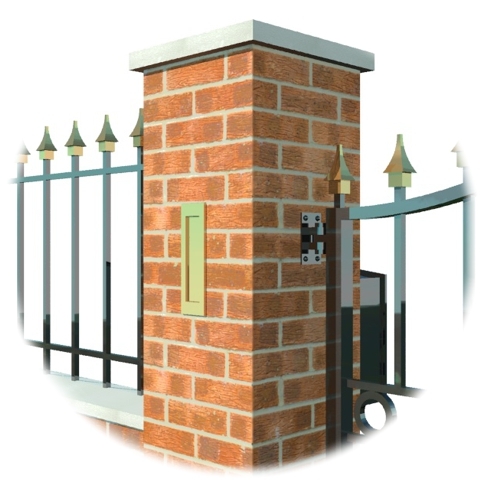


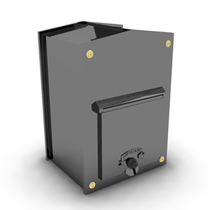
LS17 Highway vertical letter chute
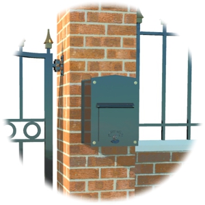
The Highway letter chute is a neat and robust solution for mail delivery through a narrow space in a brick wall.
- Models available for walls depths from 215mm to 485mm thick
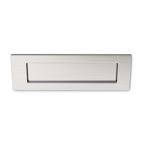
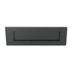
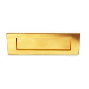
- Choice of polished and brushed chrome, textured black or polished brass letter plates
- Ideal solution for narrow brick piers
- Simple, neat solution for securely transferring mail through a brick wall or pier
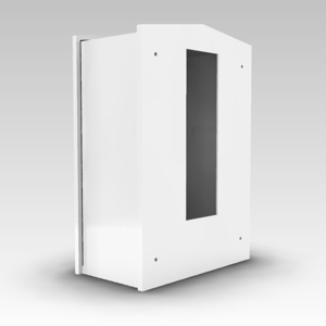
- Optional waterproof collection box available
 |
 |
 |
 |
| Standard model (350mm) | Extended model (485mm) | Fitted in a double brick wall | Optional collection box |
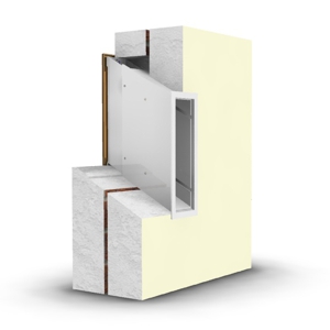
The LS17 Highway is an adjustable vertical letter chute system designed for wall or brick pier depths from 215mm to 485mm. The letter chute system is an ideal solution for transferring mail though a narrow space or brick pier. The mail can be transferred to your own container or our optional collection box. The optional collection box is lockable and supplied with 2 keys, it has been specially designed for the Highway and is totally waterproof.
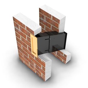
Models for brick wall or pier depths from 215mm to 485mm
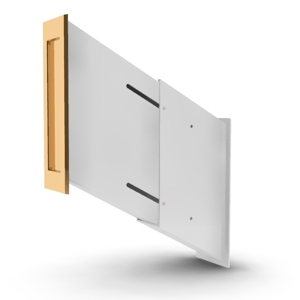
The Highway letter chute system is available in 2 models, both are fully adjustable, the standard model is suitable for fitting into brick walls or piers walls from 215mm to 350mm in depth, the extended model is designed for brick walls or piers from 350mm to 485mm deep. The two halves of the chute assembly concertina together to the correct thickness of your brick wall or pier. There are 4 clamping bolts which neatly hold the sections in place.
Optional collection box.
 |
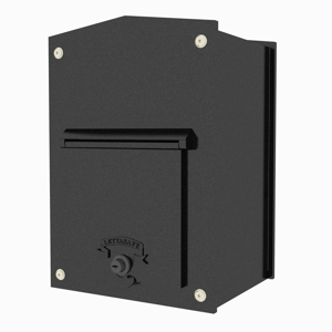 |
An optional waterproof collection box is available for both size models, the collection box is lockable and is supplied with 2 keys. There is a choice of 3 depths available (the distance from the front to the back).
The widths of all models is 295mm and the height is 425mm. The collection boxes are available in a choice of black or white with a gloss or textured finish. |
| Front view | Rear view |
**PLEASE NOTE** The Standard size (215-350) is only available in Textured White and Textured Black
LS17 Letterbox Dimensions
The Highway through the wall chute is adjustable and is designed to fit walls between 215mm and 485mm. Available in 2 models, the standard model fits brick walls or piers between 215 and 350mm, the extended model is for walls from 350mm to 485mm.
Shown below are the dimensions of the LS17 through wall chute system, all dimensions are in mm.
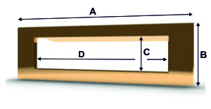 |
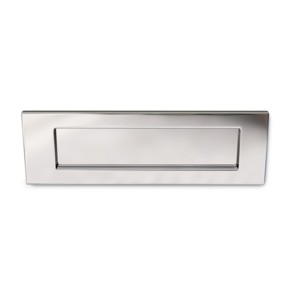
These are the dimensions of the post flap supplied with the LS17. This post flap is shown in brass but is also available in textured black and polished or brushed chrome.
|
 |
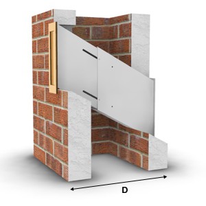
Shown below are the dimensions of the rear opening of the LS17 Chute assembly.
|
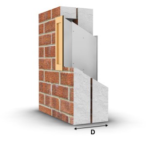 |
The LS17 chute assembly is available in a Standard and an Extended model, the Standard model can be adjusted to accommodate brick wall or pier thicknesses from 215mm to 350mm and the Extended model is suitable for wall or pier depths from 350mm to 485mm Shown below is a section showing the minimum wall thickness of the Standard model.
|
 |
|
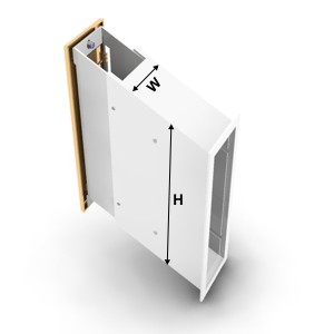 |
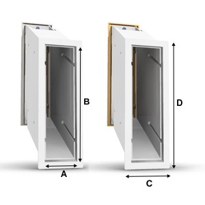
These are the dimensions of the outer (rear) chute. This assembly slides over the inner chute which is attached to the letterplate.
|
 |
 |
| LS17 Highway Fitting Instructions |
Building the LS17 Highway into a wall being built
Step 1, see fig 1
Insert the grub screws into the threaded inserts of the letterplate then secure to the front sleeve using the 2 nylocs.
Step 2, see fig 2
The rear chute has 2 sets of securing holes, the set required will depend on the depth of the wall. The diagram shows the set used for deeper walls. Place 2 nylon washers onto each of the 4 securing bolts and loosely screw into the securing holes. Position the washers as shown.
Step 3, see fig 3
Slide the 2 sections together ensuring that the securing bolts locate in the adjusting slots with a nylon washer either side of the section. Set the overall depth of the chute to a little larger than the thickness of the wall and lock the securing bolts up with the 5mm allan key.
Step 4, see figs 4, 5 and 6
Build the brickwork up to the levels of the chute assembly.
Use the chute assembly as a guide and cut the bricks to shape. The slope on the rear wall is not critical but the front wall needs to be reasonably good. The slope angle is 28 degrees.
Note the notch cutout on the front wall, the dimensions are shown below
• D = 15mm, the depth of the notch • H = 16mm, the height of the notch
Step 5, see fig 7
Continue to build the wall around the letter chute. Note that the gap above the top of the chute needs to be perpendicular to the wall, this is to allow the flap to open fully.
While building ensure that the chute assembly remains free and after building past the chute, release the 2 halves of the assembly and remove until the wall has set.
Step 6, see fig 8
Apply a small bead of clear silicon around the top and sides (not the bottom) of the flange on the rear section, then with the help of an assistant slide the front and rear sections together through the gaps in the wall. The securing bolts should locate in the adjustment slots of the front section. Ensure that there is a nylon washer either side of the adjustment slot as illustrated.
Step 7, see fig 9
Keeping the sections in place, tighten the 4 securing bolts.
Where the letterplate meets the wall, run a bead of clear silicon around the top and sides (not the bottom), also seal the internal join by running a bead of silicon on the inside of the chute where the front and rear sections meet.
Building the LS17 Highway into an existing brick wall
Step 1, see fig 1
Insert the grub screws into the threaded inserts of the letterplate then secure to the front sleeve using the 2 nylocs.
Step 2, see fig 10
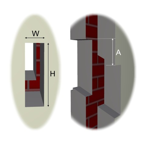
Cut a hole 296mm high by 79mm wide at the required letterplate position as shown. Note the shape of the bottom cutout, the top should be cut perpendicular to the wall.
- A = 16mm, the height of the notch at the bottom of the cutout
- B = 15mm, the depth of the bottom notch
- C = 280mm, the distance from the top of the cutout to the top of the bottom notch
- H = 296mm, the overall height of the cutout
- W = 79mm, the overall width of the cutout
- The angle of the slope is 28 degrees
Step 3, see fig 11
Cut a hole in the rear face of the wall 283mm high by 87mm wide. The horizontal position of the rear cutout should be central to the front cutout. The vertical position is determined by the depth of the wall. For a standard double brick wall (215mm thick), the top of the rear hole will be approximately 107mm below the top of the front hole. For a standard cavity wall (280mm and shown in the illustration) the distance will be approximately 142mm.
• A = 107mm for a standard double wall • A = 142mm for a standard double wall • H = 283mm, the overall height of the cutout • W = 87mm, the overall width of the cutout
The angle of the slopes is 28 degrees. The angle of the top of cutout should follow this as close as possible. The bottom cutout is not so critical and can be perpendicular to the wall.
Step 4, see fig 2
The rear chute has 2 sets of securing holes, the set required will depend on the depth of the wall. The diagram shows the set used for deeper walls. Place 2 nylon washers onto each of the 4 securing bolts and loosely screw into the securing holes. Position the washers as shown.
Step 5, see fig 8
Apply a small bead of clear silicon around the top and sides (not the bottom) of the flange on the rear section, then with the help of an assistant slide the front and rear sections together through the gaps in the wall. The securing bolts should locate in the adjustment slots of the front section. Ensure that there is a nylon washer either side of the adjustment slot as illustrated.
Step 6, see fig 9
Keeping the sections in place, tighten the 4 securing bolts.
Where the letterplate meets the wall, run a bead of clear silicon around the top and sides (not the bottom), also seal the internal join by running a bead of silicon on the inside of the chute where the front and rear sections meet.
Fig 1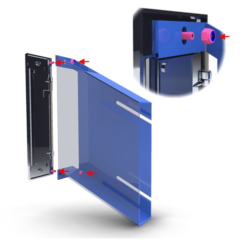 Fig 2
Fig 2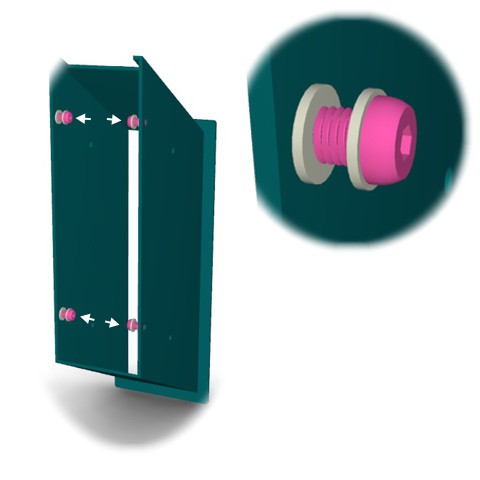
Fig 3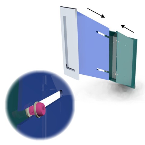 Fig 4
Fig 4
Fig 5 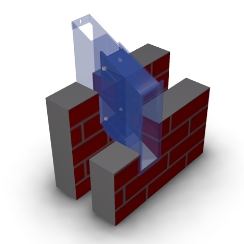 Fig 6
Fig 6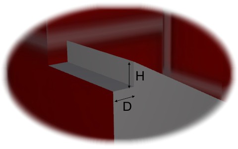
Fig 7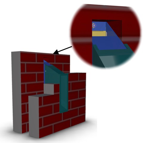 Fig 8
Fig 8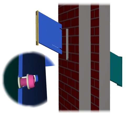
Fig 9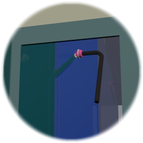 Fig 10
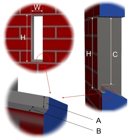
Fig 11